Healthcare data and applications are complex and require careful design choices. In a previous post, I have outlined some examples and tools for architecting LLM solutions.
One challenge of developing LLM applications for healthcare is the complexity and diversity of the architectures involved. LLMs can be used for different purposes, such as information retrieval, text generation, or knowledge extraction. Each of these tasks may require different components, such as vector stores, databases, chains, or tools. Moreover, the components may interact with each other in various ways, such as through APIs, data pipelines, or feedback loops.
To communicate the architecture of an LLM application to software developers, it is helpful to have a set of standardized symbols that can represent the different components and their interactions. Such standardized notations help in developing the conceptual (business) architecture to a logical architecture. Symbols can provide a visual and intuitive way of describing the structure and logic of an LLM application, without requiring too much technical detail or jargon. Symbols can also facilitate comparison and evaluation of different architectures and identify potential gaps or errors.
In this post, I propose a set of symbols for LLM components that are likely to be used commonly in healthcare applications. This may apply to other domains as well. Our goal is to provide a useful communication tool for software developers who want to design, implement, or understand LLM applications for healthcare.
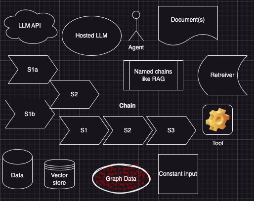
Most of the symbols above, for architecting LLM solutions, are self-explanatory and aligns with abstractions in LangChain. An LLM chain can have sequential or parallel flow, depending on the design and purpose of the application. We use the following conventions to depict the interactions between LLM components:
Other Symbols
- An arrow indicates the direction of data flow between components. For example, A -> B means that component A sends data to component B.
- A dashed arrow indicates an optional or conditional data flow between components. For example, A -/> B means that component A may or may not send data to component B, depending on some condition.
- A loop arrow indicates a feedback or reinforcement data flow between components. For example, A B means that component A and component B exchange data with each other, either to update their parameters or to improve their performance.
- A branch arrow indicates a parallel or alternative data flow between components. For example, A -|> B means that component A splits its data into two streams, one of which goes to component B and the other goes elsewhere.
- A merge arrow indicates a joint or combined data flow between components. For example, A B means that component A and component B join their data into one stream, which goes to another component.
- A label above an arrow indicates the type or format of the data that flows between components. For example, A ->[text] B means that component A sends textual data to component B.
I would love to hear your suggestions, feedback and input on how to improve this process!
- V. LLM-in-the-Loop CQL execution with unstructured data and FHIR terminology support - June 4, 2025
- IV. DocumentReference hook in CQL execution - June 3, 2025
- III. MedPromptJS: Simplifying GenAI Application Development - June 2, 2025
The algorithm journey map: a tangible approach to implementing AI solutions in healthcare: https://www.nature.com/articles/s41746-024-01061-4
Pingback: To or not to LangChain - Bell Eapen MD, PhD.
Pingback: Grounding vs RAG in Healthcare Applications - Bell Eapen MD, PhD.
Pingback: Why is RAG not suitable for all Generative AI applications in healthcare?